How to test diodes and transistors
|
||||
| Shop for Multimeters | ||||
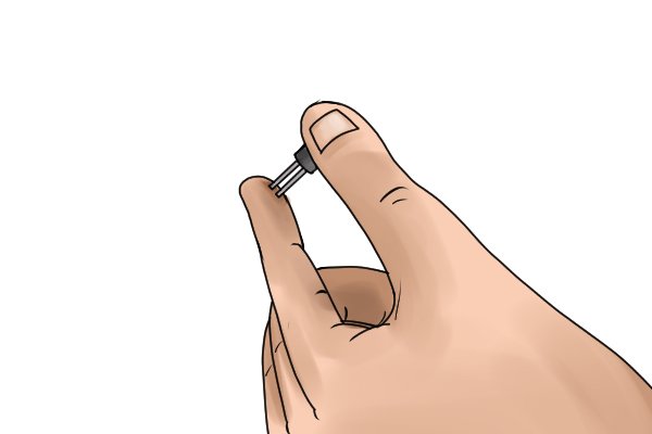 |
Step 1 – Prepare diode or transistorIt is best to test diodes and transistors out of circuit, however if this is not possible, ensure the power is off and capacitors are discharged. |
|||
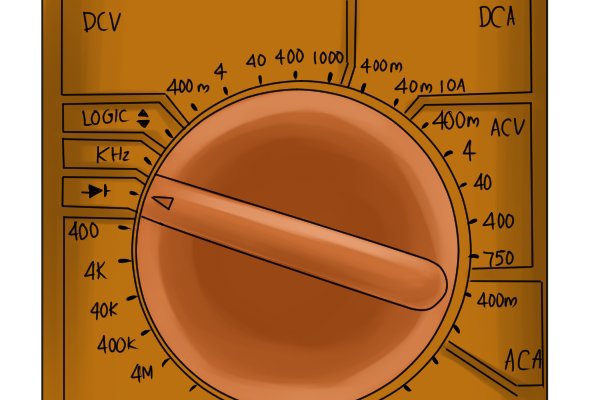 |
Step 2 – Set multimeterRotate the dial to the diode symbol. If this is not the only symbol at this point, press the shift / mode button until you are in the ‘diode and transistor testing’ mode. |
|||
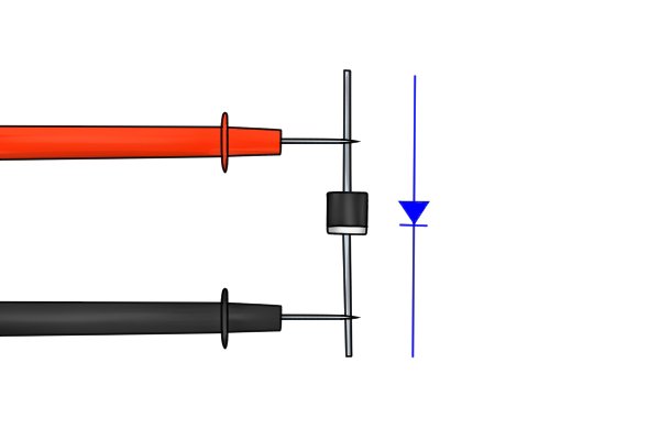 |
Step 3 – Place probesFor diodes…Place the positive (red) probe on the positive terminal of the diode and the negative (black) probe on the negative terminal. |
|||
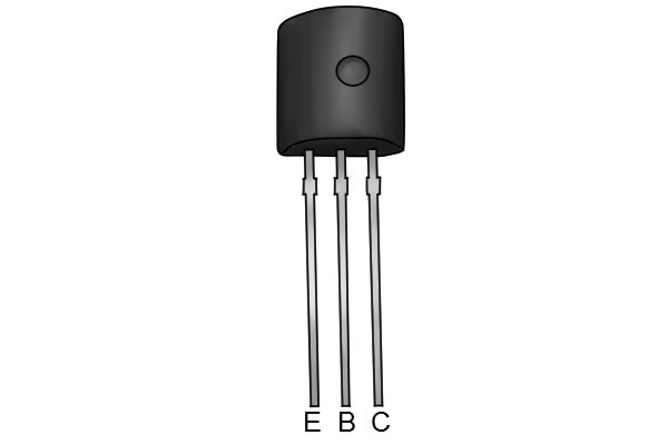 |
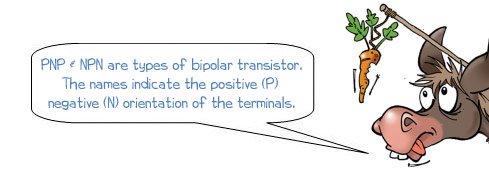
For transistors…Transistors are tested to check that current flows in one direction, but not the other. The placement of the probes is slightly more complicated because there are three terminals and you first need to determine which is which. As the placement varies with different brands and types, searching the internet for the number on your transistor should tell you which of the leads is which: there will be a base, collector and emitter (B, C, E). |
|||
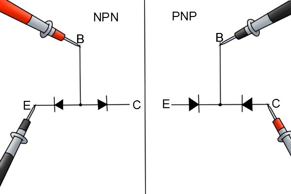 |
For NPN transistors, electricity should flow from the base to the collector and from the base to the emitter. So the red probe should be on the base in both cases and the black placed on either the collector or emitter to produce a reading. Repeating the process but with the black probe on the base should yield no results (OL (open loop) displayed on most DDM’s).
For PNP transistors, the electricity should flow from the collector to the base and the emitter to the base. Therefore, the black probe should remain on the base while the red probe placed on either the collector or emitter. Repeating the process but with the red probe on the base should yield no results (OL (open loop) displayed on most DDM’s). |
|||
 |
||||
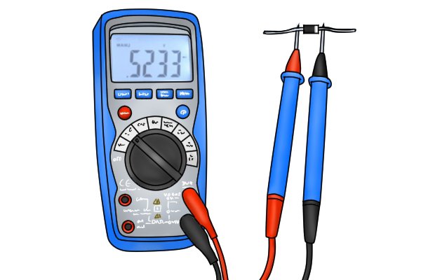 |
Step 4 – ResultsThe diode setting on a multimeter measures the voltage drop across the diode or transistor, and this should ideally be between 0.5v and 0.8v. The value will be seen on the display and, if it is a successful reading, there may be a short beep to indicate a good diode.
If the voltage drop is too low, a continuous beep may sound, indicating a short circuit. Whether audio or displayed results are presented varies depending on multimeter used. |
|||
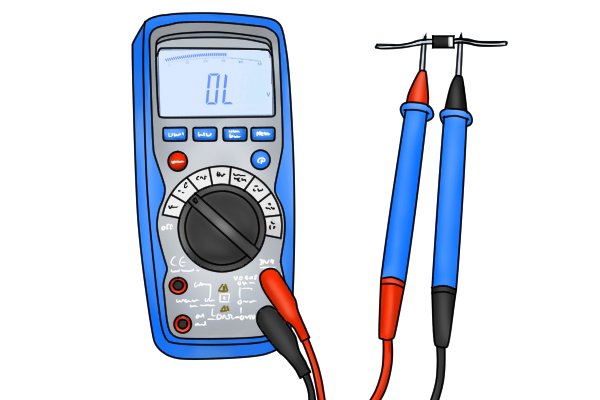 |
Step 5 – ReverseReverse the probes to ensure that the diode or transistor is not conducting electrons backwards. This should show the OL reading on the screen, indicating an open loop and no continuity over the diode. Any other reading means that the diode or transistor is conducting electricity in the wrong direction and is therefore faulty. |
|||
Alternative diode and transistor testing method |
||||
|
Some multimters have specialised sockets, where diodes and transistors simply slot in for testing. This may be labelled Hfe. |
||||


