What is a multimeter used for? |
||||
| Shop for Multimeters | ||||
|
Multimeters can be used by anyone, but are really a professional instrument for those with electrical know-how. Anyone planning on using a multimeter should carefully read the instructions for their specific model before beginning any work.
Multimeters can be used for a wide range of electrical tasks, in several disciplines, including: home and automotive electrics, electronics and professional applications. |
|||
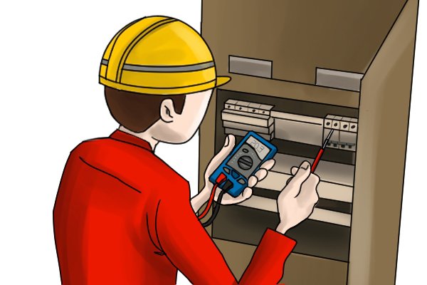 |
The main purpose of a multimeter is to check the safety of electrical equipment, and that components are functioning as they should. | |||
|
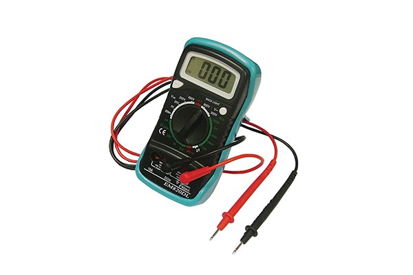
The most common functions of a multimeter are for checking voltage, current and resistance. There are almost always more than these three settings though. Some of the functions will be more useful than others and will be dependent on the type of work they are to be used on.
For example, when used in electronics, voltage, resistance and continuity will be the top requirements, whilst the temperature, transistor and duty cycle testing will be superfluous. |
|||
Measuring voltage |
||||
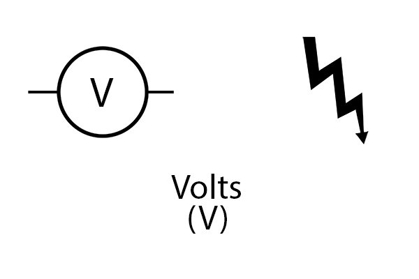 |
All multimeters should be able to measure voltage, like a voltmeter. The voltage symbol will simply be a ‘V’. However, this can be further broken down into millivolts (mV) or microvolts (μV). One millivolt is the equivalent of one thousandth of a volt and one microvolt is one millionth of a volt. This makes multimeters more precise than voltage detectors and testers.
For more information on these instruments, see: {{widget type=”cms/widget_page_link” anchor_text=”Voltage Detectors and Testers” title=”Voltage Detectors and Testers” template=”cms/widget/link/link_inline.phtml” page_id=”2209″}}. |
|||
Measuring current |
||||
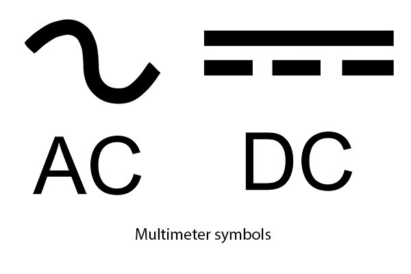 |
Another of a multimeter’s main functions is to measure current. All multimeters will have the capability to act as an ammeter, measuring amps in series with the circuit. The symbols for measuring current are split in to AC and DC and will be followed by an ‘A’ for amps on the multimeter screen, sockets and/or dial. |
|||
Measuring resistance |
||||
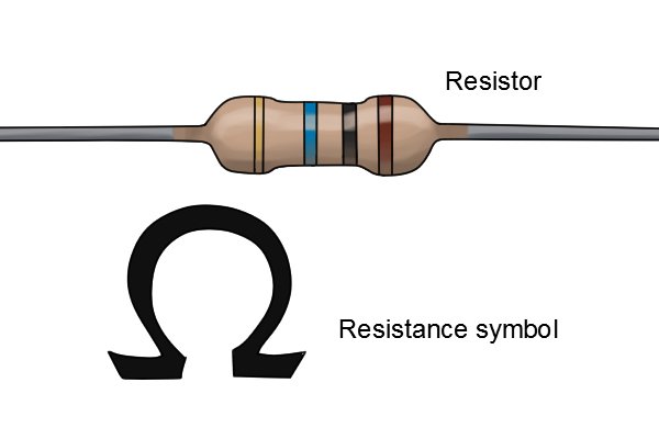 |
Most, if not all, multimeters will have the ability to measure resistance. The ohmmeter on a multimeter will be represented by the Ω symbol. |
|||
Checking continuity |
||||
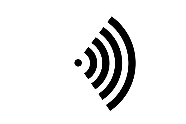 |
Multimeters with the ability to test continuity will have a symbol which looks like sound waves emitting from a dot. Continuity must be tested whilst the test item has no power (is switched off). The continuity is tested by applying a small amount of voltage through the appliance from the multimeter. |
|||
Checking polarity |
||||
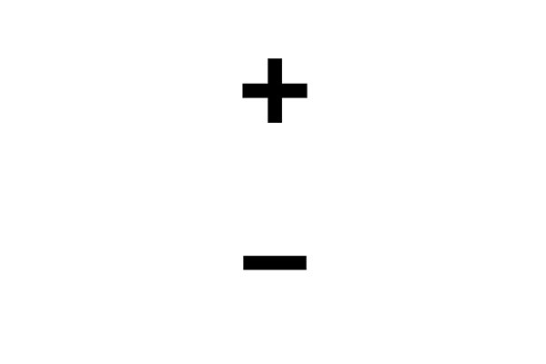 |
Polarity testing does not require its own setting as it is a result of voltage testing. As long as the cables are connected correctly then a positive voltage reading signifies the red cable as the positive polarity point, and if the voltage reading is negative then the black cable is the positive point. |
|||
Measuring capacitance |
||||
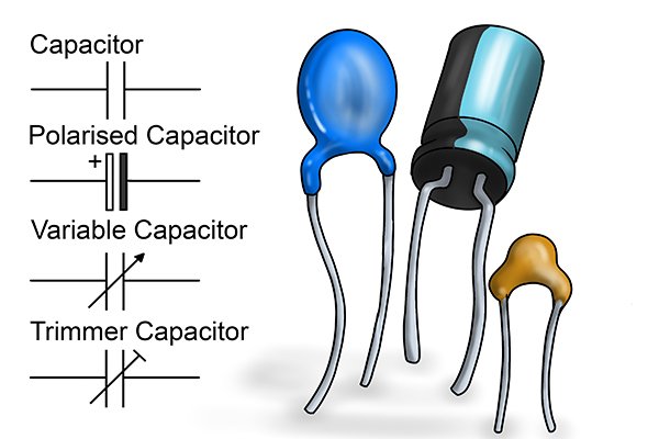 |
If the multimeter has a capacitance setting, it will usually be represented by the letters CAP and the units of measurement will be displayed as mF, μF or nF (millifarads, microfarads or nanofarads) on the display, dial and/ or sockets. |
|||
Measuring frequency |
||||
 |
Frequency settings, if available, will be represented by the unit of measurement: Hz (hertz) |
|||
Measuring temperature |
||||
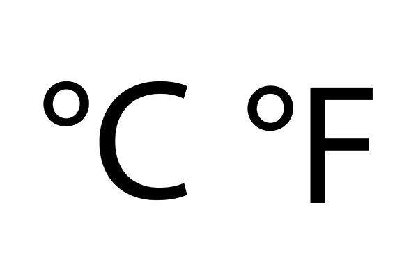 |
The temperature settiing availble on some multimeters is usually in both °C and °F units. These will also be the symbols used to represent the temperature function. |
|||
Measuring duty cycle |
||||
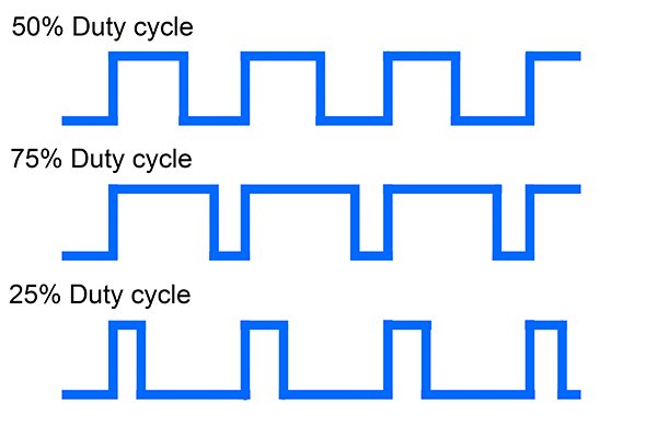 |
Duty cycle is the period of activity during a given amount of time, as a percentage. On multimeters with the capability, the most common way to test duty cycle will include double pressing the Hz button to set the device to duty cycle. The reading will be given as a percentage. |
|||
Diode and transistor testing |
||||
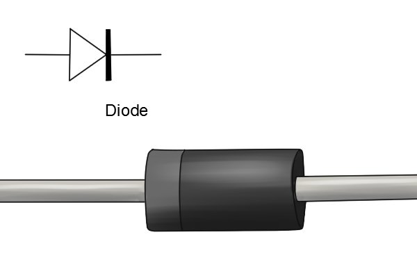 |
Some multimeters can test diodes and transistors, these are components which can be added to circuits.
Diodes only allow current to flow in a single direction. There are different types including LEDs (Light Emitting Diodes) which are low energy lamps used in many applications. |
|||
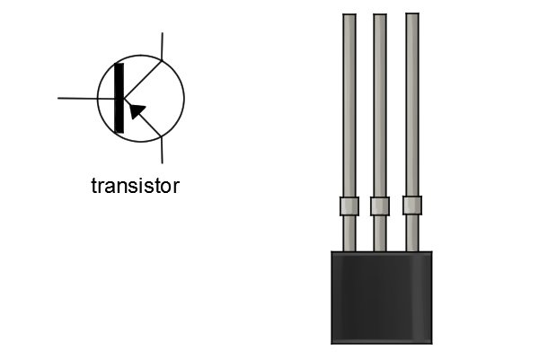 |
Transistors are like more complex diodes, and not only control the direction of electron flow but also the amount that flows. Transistors are found in most electronic circuits.
The multimeter tests whether diodes and transistors are functioning properly; allowing or preventing electricity flow in certain directions. On the compatible multimeters, there is usually a provision for PNP and NPN, the most common types of transistor. |
|||


